The Fool's Quarter
Line Diagram
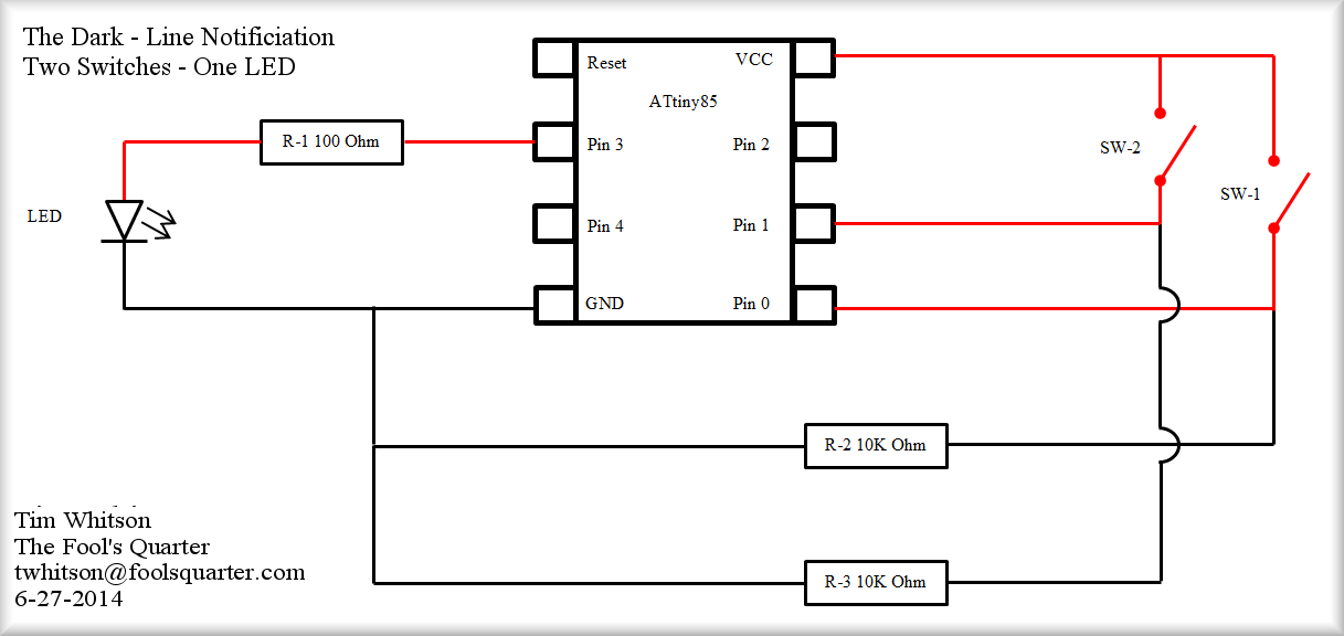
The concept behind this controller was to have a switch located within the haunt were the actors could signal the person controller admission when the next group was clear to come in. It is important to keep the line going as fast as possible but not have the guests run into each other. Initally we thought a simple LED that would illuminate when a button was pushed would do the trick. What if the person controlling the line was not paying attention, some hot girl might be the next in line... It was determine the light should stay on until the acknowledged by pushing a button at the entrance. A perfect use for the ATtiny85.
You can size the resistor for the LED to whatever you need. I didn't include it as part of the circuit board. I figured I'd install it inline with the LED. For the push button you have to have a pull up resistor. Without it you will get quite a bit of spurious hits and the push button will not work. I have found I don't really need to debounce my pushbuttons if I use the resistor.
One quick note, I don't show where the power comes in on this diagram. You can use 3 to 5 vdc with the positive hooking up to the VCC pin and the negative hooking up to GND.
Printed Circuit Board Design
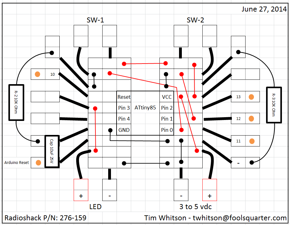
I decided to start using Excel to draw up my printed circuit boards (PCB). I'm an Excel geek... Anyway, I find it helpful. I can't always say the boards come out exactly like I draw them, but they are close. One nice thing I noticed on this project while I was drawing the PCB was I had room to install programming pins and the capacitor. I had to turn the capacitor and use a different hole for the negative side, but all in all it came out like I planned it. As I stated before, adding the programming pins is a great benefit. It allows you to tweak the program after you assembled the PCB.
Printed Circuit Board Completed
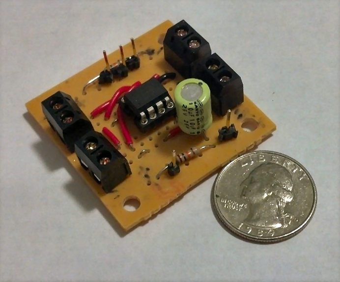
As you can see it's quite small. I really like the Radioshack 276-159 PCB's. The way they are laid out makes it perfect for the ATtiny85. I'd show you my solder job but it's not the greatest. I just purchased a pencil sized soldering iron. I have high hopes to improve my technic soon...
Final Product
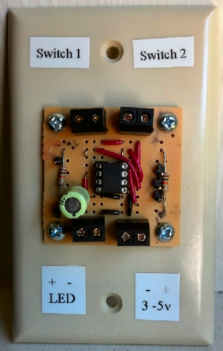
Here is the final product ready to hang on the wall and wire it in. I bought 50 of those two screw PCB terminal blocks on eBay. They are not the best quality. They don't line up very well. But they do work and they were cheap.
I used a blank wall plate to mount this on. I was looking for a piece of plastic to attached it too. This was cheap and it met all the criteria I needed. Since I plan on using this PCB from Radioshack on quite a few ATtiny85 projects you'll probably see this mounting technic again.
Program:
/*
Crowd Control for the Dark
Used to let the person controlling entrance into The Dark know when the next person can enter.
Pushbutton 1 will turn on the LED. Pushbutton 2 turns it off.
Written by Tim Whitson
http://www.foolsquarter.com
for the Milburn Manor Haunted House in Hubbard, OR
http://www.milburnmanor.com
June 28, 2014
*/
// set pin numbers:
int button1Pin = 0;
int button2Pin = 1;
int ledPin = 3;
byte leds = 0;
void setup() {
// initialize the LED pin as an output:
pinMode(ledPin, OUTPUT);
// initialize the pushbutton pins as inputs:
pinMode(button1Pin, INPUT);
pinMode(button2Pin, INPUT);
}
void loop(){
// read pushbutton 1 to determine if it's been pressed:
if (digitalRead(button1Pin) == HIGH){
// turns LED on:
digitalWrite(ledPin, HIGH);
}
// read pushbutton 2 to determine if it's been pressed:
if (digitalRead(button2Pin) == HIGH){
// turns LED off:
digitalWrite(ledPin, LOW);
}
}