
- The Beginnings...
When I first heard about this chip my head became full of possiblities on how I could automatic the little functions we do. But of course the first thing I needed to do is see if I could replicate something we do with a Prop-1 and audio card.
I set the card up to have one push button input, three LED outputs (with built in transistor circuits), and one audio trigger output.
Using the transistor circuit, with 2N2222 NPN transistors, I am able to control up to 500mA of LED or approximately 25 per channel. The Arduino UNO is only rated at 40mA per channel, is does have several more channels.
I also wanted to include the programming pins and the capacitor. This made it easier to tweak the program and I'm sure I'd lose the capacitor if I kept it loose.
I really like PRICOM Designs audio players. They are simple, easy to trigger, and come in a single sound or four sound design.
The Schematic
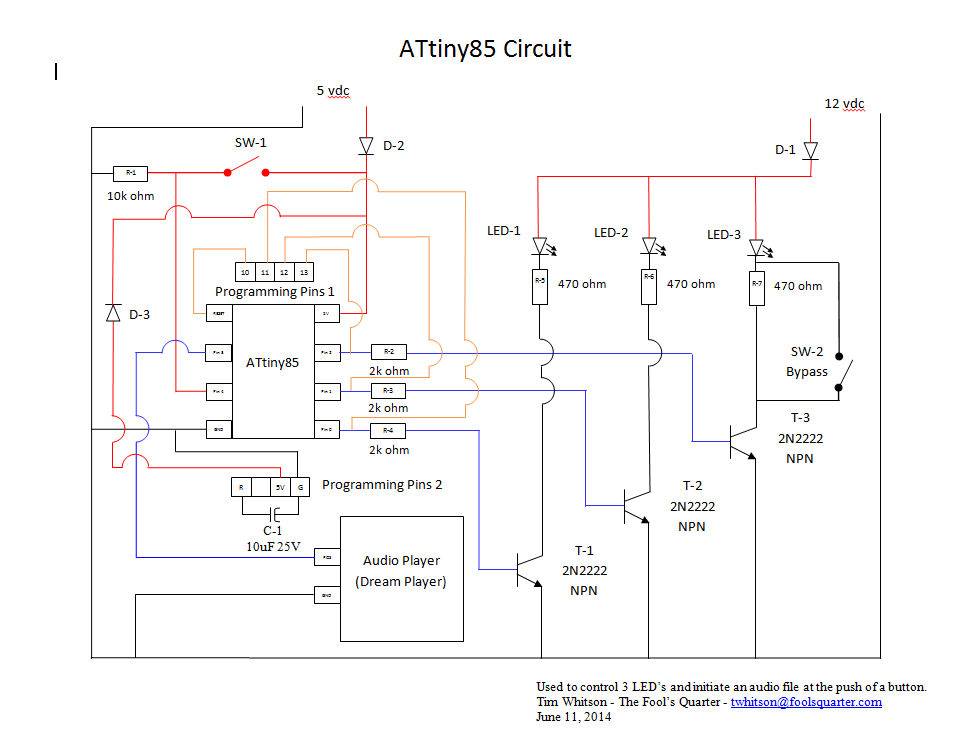
This diagram is pretty extensive. I used the Radioshack 276-168B PCB. It has pre-connected holes to allow wiring the components easier. I included three diodes to protect the three different power sources, the 5 vdc normal power to the chip, power from the UNO while programing and the 12 vdc power for running the LED's. There is a bypass switch on LED-3, this would be to bypass the resistor to allow running a relay instead of an LED. I didn't install this on the board I built, I had planned on using two pins and a jumper instead of a switch, cheaper and easier. Make sure you include the 10k Ohm pull up resistor on the switch, it will help get rid of the spurious activations, I also find I don't need to use debounce the switch. One thing to note, all grounds must be tied together for this circuit to work. The transistors will not switch if the 12 vdc and the 5 vdc grounds are not connected.
Printed Circuit Board Layout
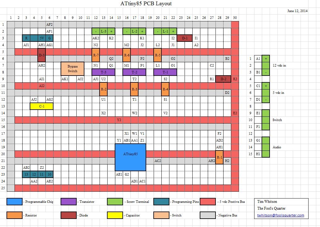
I used Excel to draw up the PCB layout. The letter / number codes are for the wiring. You'll notice I am not patient enough to solder it exactly as I drew it, at least not the first time around. I was under a time crunch, wanting to show it off and such. It can be laid out like I drew it, I just need to get creative on how I run the wires. Basically the terminal blocks take up too much room. I'll need to run the wire on the bottom of the circuit board and go under the terminal block. I recommend thin solder and a fine tip on your soldering iron. Practice solding. Radioshack sells quite a few different PCB designs you can play with.
Final Product
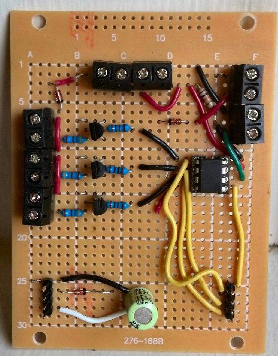
As you can see the final working product. I will need to mount it and label it so I can remember what is what. But this is ready to put into the haunted house. At a push of a button it'll control up to three sets of leds, up to 25 LEDs per set, and start an audio file. At the bottom you can see the 10uf/25v capacitor and the programming pins. On the left you see the three 2N2222 transistors which allow up to 500 mA of current at 12 vdc. At the top are the 12 and 5 vdc power input terminals. On the right side is the switch imput with it's pull up resistor and the sound tigger terminals. As noted above, this board does not have the jumper around transistor 3. It can still be added in. This would allow the that channel to operator a 12v light or relay.
This was a fun project, but for a few dollars more you can buy an Arduino Uno and have more pins to play with. I will make another one just to prove the PCB layout.